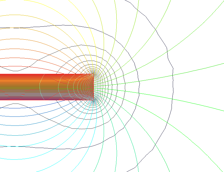
Fig. 16
Close-up of rectangular magnet showing field lines and field density curves
In the main text it was shown, that through the use of the phenomenon of levitation magnets for counteraction to the gravitation in the sector A8 - O - A11 (Figures 2, 5 and 8) it becomes possible long-term rotation of the motor shaft.
Initially, the possibility of providing additional torque on the motor shaft, thanks to the use of the repulsive interaction between the magnets in the remaining areas (sectors) of rotation of the movable loads, was not seemed obvious. It was necessary to become familiar with many of articles on the Internet, in which may have been considered similar questions. Unfortunately, to find something useful in this regard have not turned out possible. Therefore, it have required to consider this difficult question on my own.
The sequence of analysis of the interaction of magnets, which has been applied here, to some extent similar to the methodology set forth in article “PM3 Permanent magnet machine” (Presented by K Pullo, Jan. 21, 2005)[33]. But unfortunately, herewith has not been possible the access to the program for calculating, which had been used by the author ("Finite Element Method Magnetics"[34]), and even has not been the certainty that this program, or any like it, would allow to calculate the force interaction of the magnets of required geometry.
When developing methodology for analyzing the force interoperation opposing fields of the magnets, was taken into account the character of the force field of a stationary magnet of rectangular shape, which is shown here, in Fig. 16. The Figure 16 is the copy of the illustration given in the article “Magnet Man”[35].
This graphic image of the magnet with its field lines and field density curves had been converted in an object that can be handled by technical means of the program "AutoCAD", and, by using tools of that program, was made an attempt to find an answer to this question.
*
* * *
Consider at first the most simple example by using here methodology for calculating the resultant force interoperation of opposing fields of stationary and movable magnets. "Simplicity" of this example is determined by the fact that the trajectory displacement of the center of gravity of the movable cylindrical load, which is equipped by the annular magnets, is a straight line, parallel to the surface of the earth.
Movement of the load is implemented due to impact of an external force on the center of its gravity.
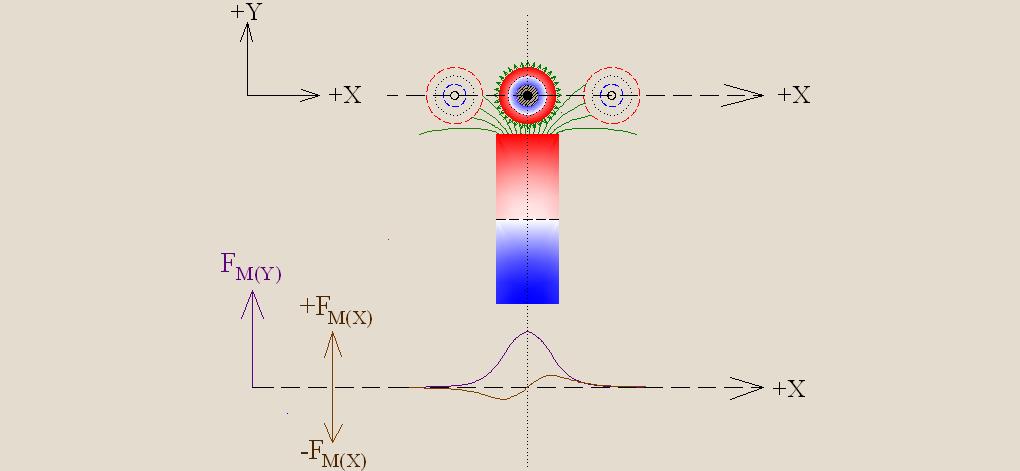
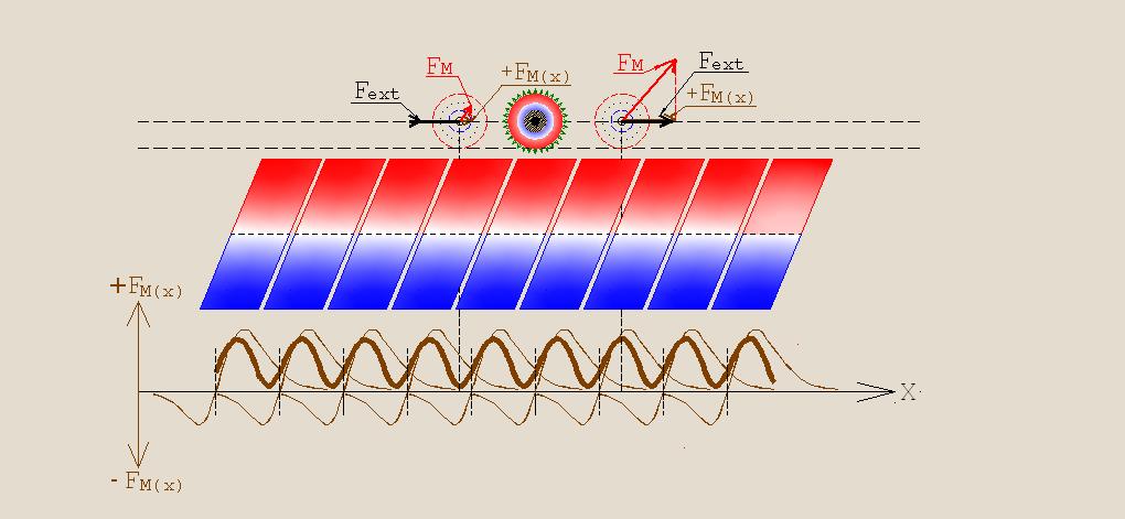
In the upper part of Fig. 17 is shown the cross section of the stationary magnet of rectangular shape, and several moments of moving the load during its movement over the stationary magnet. The contours of the cross sections of moving load are shown by dashed lines. The middle part of image of the cross section of the stationary magnet has been cut off (relative to its length) in order to reduce occupied space in the figure. The structure of the cylindrical load is explained in section 7 of the main text. The cross section plane of the magnets is vertical relative to the surface the earth, and passes through the centers of gravity interacting magnets. The coincidence of the polarities opposing surfaces of the stationary and moving magnets determines the repulsive character of their force interaction.

In Fig. 17 introduced the following denotations:
Fext — vector of external force action on the center of gravity movable load;
Fg — vector of the gravitational force action on the center of gravity movable load;
FM — vector of the magnetic force action on the center of gravity movable load (magnitude and direction of this vector are determined by the counteraction of identical poles of the stationary and moving magnets);
+FM(X) — component of the vector FM, which coincides with the direction of the vector Fext, i.e. facilitates to the movement in the required direction;
−FM(X) — component of the vector Fm, which is opposite towards the vector Fext, i.e. impedes to the movement in the desired direction;
+FM(Y) — component of the vector FM, which is opposite towards the vector Fg, i.e. counteracts to the gravitational effect on the moving load;
Lpl — the length of the plane (Lplane). This length characterizes the portion of the pole surface of the stationary magnet which interacts with a magnet of the movable load that passes over it. The size of this length depends on the location of center of gravity of the movable load in the trajectory of its movement.
Lpl(max) — is the maximum possible value of Lpl ;
Lg — the length of the air gap (Lgap). This is current value of the air gap between the poles of the interacting magnets. Lg – is a segment of a straight line directed from the midpoint of the interval Lpl to the current location of center of gravity of the passing load. The value of this segment is defined as the minimum distance from the midpoint of the interval Lpl to the nearest point of the cylindrical surface of the moving load.
Lg(min) — is the minimum possible value of Lg.
Notes:
Graph of the dependence of the numerical values of the vector FM(X) (taking into account the sign) from the value of the X-coordinate of center of gravity of the moving load is drawn on the points for which the coordinate FM(X) is calculated using the formula:
FM(X) = Nx· K(Lpl)·Kg(Lg)·cosφ.
Graph of the dependence of the numerical values of the vector FM(Y) (taking into account the sign) from the value of the X-coordinate of center of gravity of the moving load is drawn on the points for which the coordinate FM(Y) is calculated using the formula:
FM(Y) = Ny· K(Lpl)·Kg(Lg)·sinφ.
In these formulas, accepted the following notation:
Nx and Ny — scale coefficients, the numerical values of which are chosen such as to provide greater visibility of the graphic image.
K(Lpl) = Lpl /Lpl(max) — coefficient reflecting the ratio between the size of that portion of the pole’s surface of the stationary magnet which interacts with a magnet of the moving load that passes over it and the maximum possible value of this surface. The coefficient K(Lpl) varies in the range 0 ... 1 in the process of passing moving load over a stationary magnet.
Kg(Lg) = Lg(min)2/ Lg2 — is the coefficient taking into account the quadratic character of dependence of the force counteracting of the magnets from the size of air gap between them.
In calculating the coordinates of points for plotting the charts (which are depicted in the lower part of Fig. 17) both coefficients Nx and Ny were taken equal to the number 20.
Of course, evaluate the accuracy of this method of calculation is very difficult. The numerical values of the lengths of Lpl were determined on the basis of the distribution of the magnetic field near a stationary magnet, shown in Fig. 16, which is two-dimensional characteristic of the field, although in reality the magnetic field is distributed in three-dimensional space. When calculating was assumed that the external field of a ring magnet uniformly, but it can also be an approximation, especially if will be applied the magnets of type "Halbach cylinder"[9]. From these charts impossible to speak about the actual absolute value of vectors FM(X) and FM(Y) . These calculations do not take into account nor characteristics of magnetic materials, nor actual geometric dimensions of opposing magnets, nor the quality of their magnetization. But the character of the relative change of the force interaction of counteracting magnets in the process of movement of the load (equipped with a ring shaped magnets) along a rectilinear trajectory can be estimated with sufficient reliability.
The results of calculation and the corresponding plotting in Fig. 17 allow the following conclusions:
In Fig. 18 is represented more complete picture of the interaction between the stationary and movable magnets, which will be used for further compositions. In the central part of the figure are shown the total cross sections of a stationary magnet, and the movable load which is equipped with annular magnets. In the lower part of the figure are shown the change in values of the vectors FM(Y) and FM(X) in the process of moving the center of gravity of the load along the linear trajectory. Herewith in order to comfort and better visibility of further constructions in Figure 18, in contrast to Fig. 17, the coefficients Nx and Ny were taken equal to the number 10.
*
* * *
We will place now under the straight-line trajectory of movement of the cylindrical load (equipped with annular magnets) a lot of (network) of stationary magnets of rectangular shape, as it shown in Fig. 19. In the lower part the figure are shown the graphs which reflect the net force interaction of the magnets during the movement of the load along the X-axis.

Here also, as in Figure 18, the scale coefficients Nx and Ny are assumed as the number of 10. The resulting curves for changes in the values of the vectors FM(Y) and FM(X) as a function of the coordinate X are shown in that figure by thick lines. Figure 19 graphically reflects the fact, that at selected geometric ratios of the magnets which counteract each other, and with the chosen trajectory of movement of the load, the main energy of the force action of the magnets is expended on counteraction to the gravitational impact (vector Fg) on the load. The resulting curve of change in the magnitude vector ±FM(X), as a function of the X-coordinate, passes very close to the X-axis, crossing it at the points that were mentioned earlier as "breakpoints". Thus, the magnets do not exert practically force action on the motion (movement) of loads along the X-axis. That is, the movement of loads in this direction can only be done due to an external force (Fext).
*
* * *
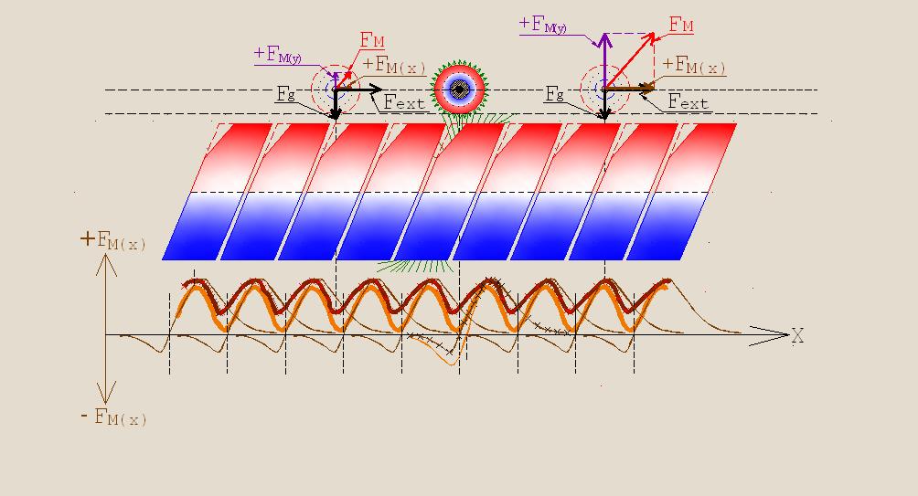
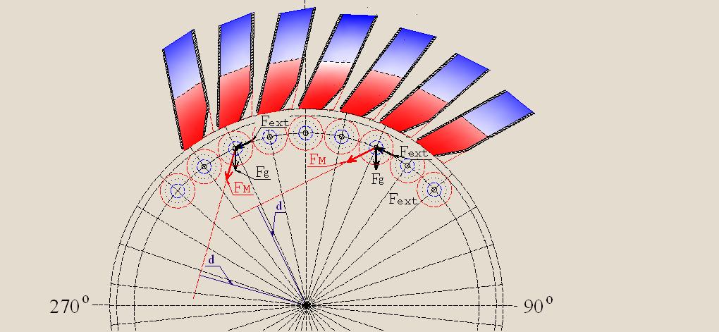
With the help of Fig. 20 we consider the force’s interaction of the magnets, turning the rectilinear horizontal trajectory of the centers of gravity of loads in a circular. At the same time will assume initially, that the circular trajectory of the centers of gravity of loads is located in the horizontal plane, i.e. in a plane parallel to the earth's surface. Vector of external force action (Fext) provides rotation of the loads about the axis O. Vector of the gravitational force action (Fg) is not shown in Fig. 20, as at the horizontal arrangement of the circular trajectory it does not affect on the resulting torque. Vectors of force's interaction between the magnets, which operate on the centers of gravity of the moving loads, correspond to the vectors FM(Y) which where shown in Figures 17, 18, 19, are denoted here by the same symbol FM(Y). Directions of these vectors at any point in moving of the centers of gravity loads along a circular trajectory intersect the axis of rotation (at the point O), that is, at such mutual arrangement of the magnets, neither additional impact on the resultant torque will not be created. Figure 20 does not show the vectors corresponding to the vectors ±FM(X), shown in Figures 17, 18, 19, because and here, also as in the case of movement of loads along a rectilinear trajectory, the net effect of a network of stationary magnets on the movement of loads along a circular trajectory will be practically zero.
However, if the plane in which the circular trajectory of rotation of the centers of gravity of the loads is located perpendicularly to the horizontal surface of the Earth, as it was with the disks and movable loads in the structure that was considered in the main text, the force vectors Fg and FM(Y) will interact, and their interaction at different points of the trajectory will be different.
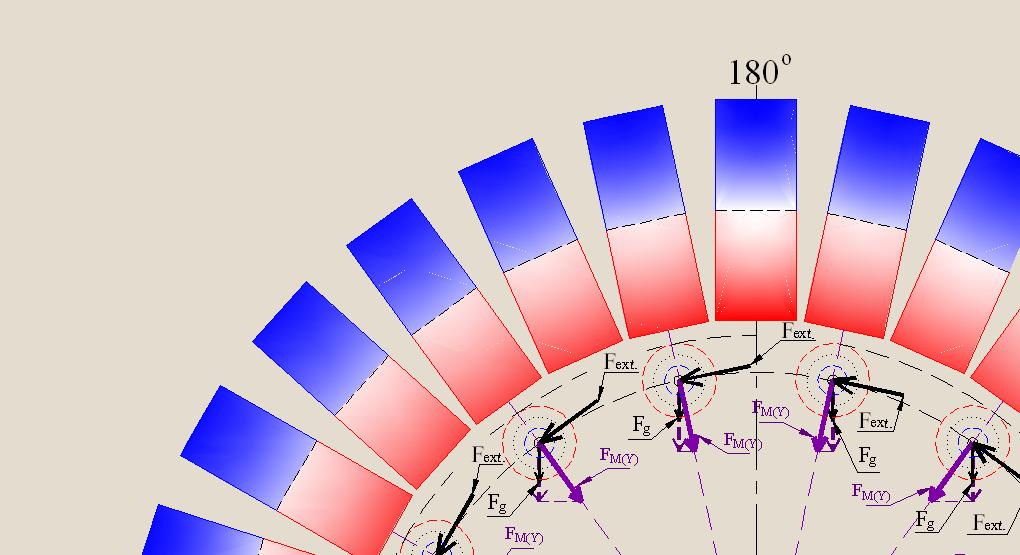
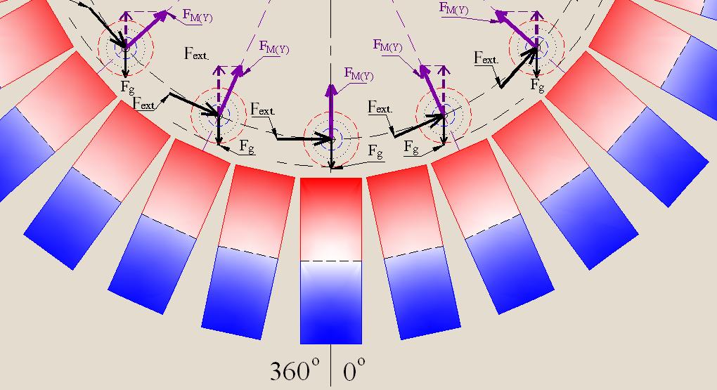
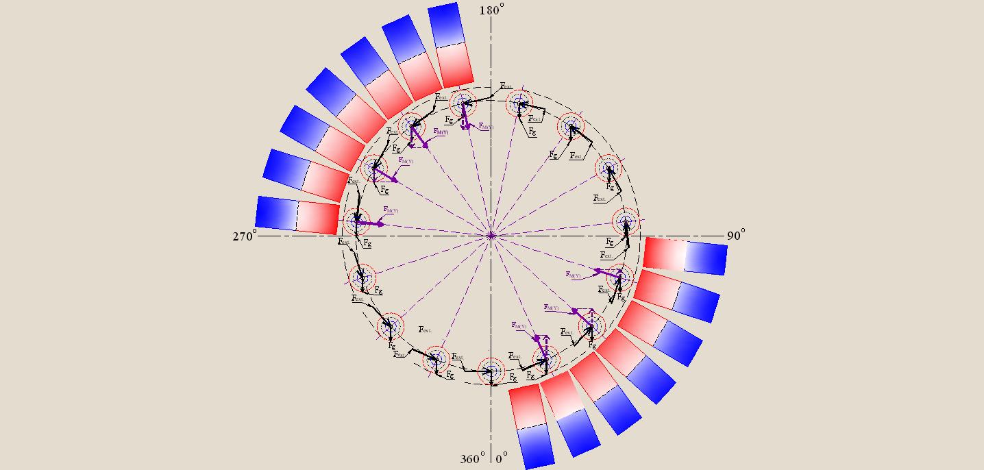
Let's consider Figure 21, which shows the cross section of the magnets by the plane in the case of continuous placement of the stationary magnets under the entire closed circular trajectory of the cylindrical loads fitted up with the annular magnets. At the same time it is assumed that the plane of cross section, in which lies the trajectory of movement of the centers of gravity of the loads, is located perpendicularly to the surface of the Earth.
In Fig. 21 we can see that at each point of location of the center of gravity of the moving load is carried out the interaction between the vector FM(Y) and the vector of gravitational effect to the load Fg. The result of this interaction at each point of the trajectory is different, and depends on the angular distance between these vectors which varies in the process movement of the load.
In the figures 22 and 23 the interaction of these vectors are represented in enlarged form in certain sectors of the circle.
However, if we summarize the impact of the interaction of these vectors throughout the closed circular orbit of the movement of loads, i.e. impact on the resultant torque, will appear that the use of magnets in such a device is useless. If there is no an external torque effort (Fext), the resultant torque must be equal to zero, i.e. in this system will be observed condition of a stable equilibrium. Thus, the magnets in this design will not produce any additional effect on the resultant torque. The magnitude and character of the net torque can be resulted here only by the external force (Fext).
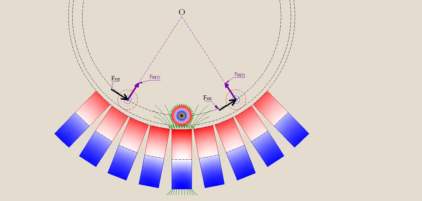
The state of the system will be changed if the stationary magnets will be placed not under the entire circular trajectory, as it was shown in Fig. 21, but only in the sectors 0° — 90° and 180° — 270°, as it shown in Fig. 24, and, on a larger scale, - in Figures 25 and 26.
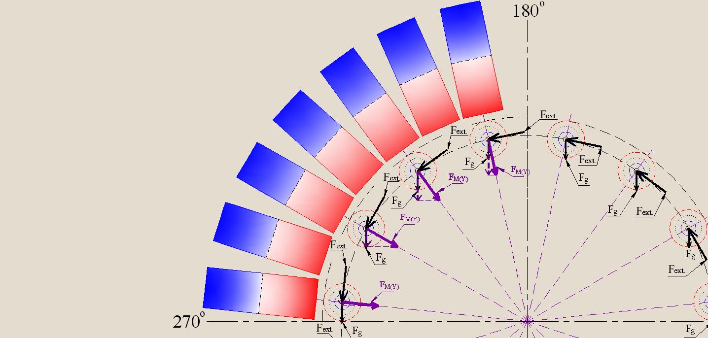

Here you can see that by passing loads sector 180° — 270° projections of the vectors FM(Y) coincide in direction with the vectors of the gravitational effects on the loads (Fg), but when passing sector 0° — 90° projection of such vectors are opposite in direction to the vectors Fg.
In such a system the use of magnets can be useful since the resultant torque created by force interaction of stationary and movable magnets is not zero and corresponds to the direction of impact of the external torque effort (Fext).
*
* * *
Then the question arises: "Is it possible to strengthen this positive effect by changing the shape and direction of initial magnetization of the stationary magnets?"
Let us return to consideration the results of counteraction opposing magnetic fields, provided that the trajectory of the cylindrical loads is straight-line.
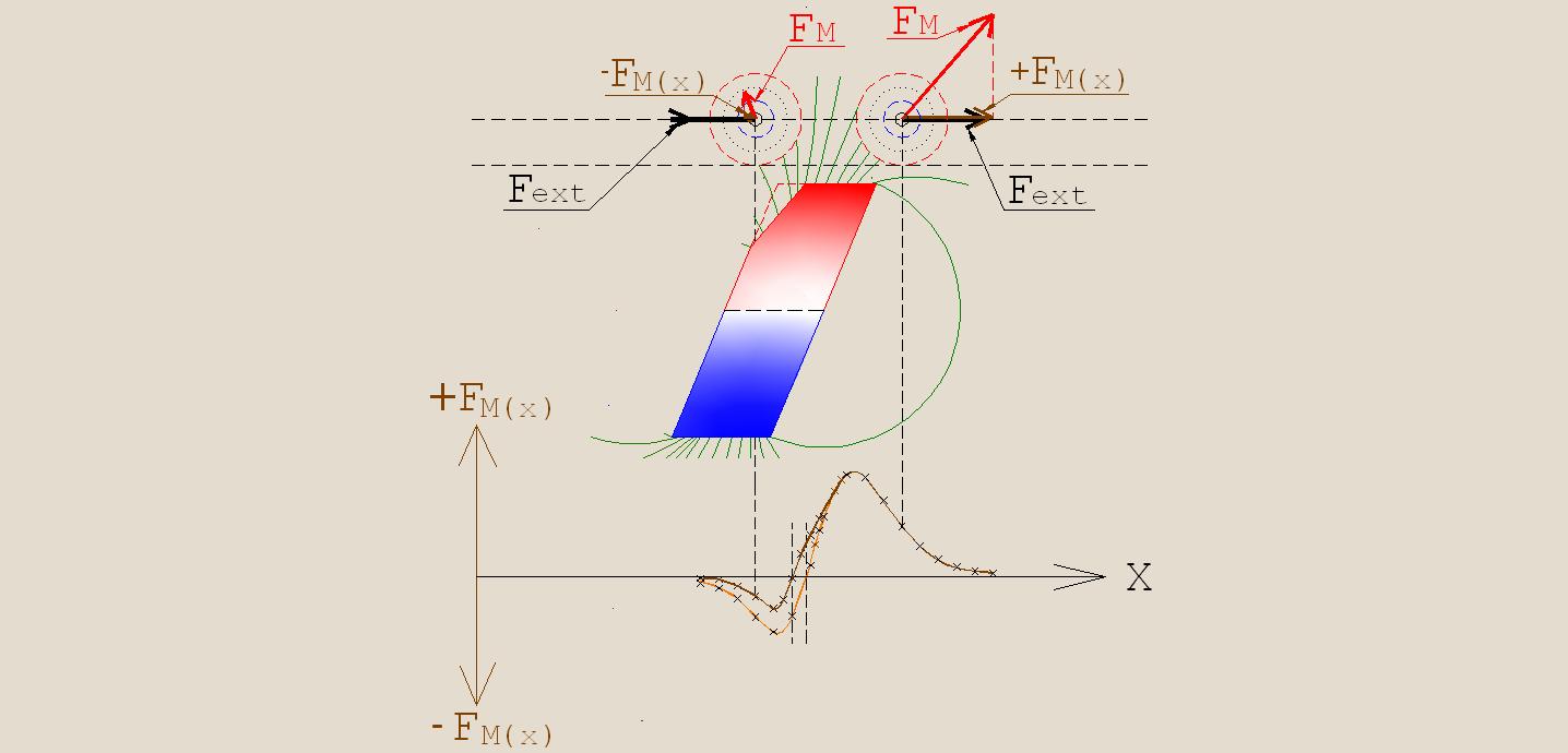
In Figures 27 and 28, in contrast to the Figures 17 and 18, the shape of a stationary magnet was changed. Its long parallel sides are inclined at some angle to the right from the vertical. Under the same angle, was performed initial magnetization. In the lower parts of these figures are shown the change in values of the vectors ±FM(X) in the process of moving the center of gravity of the load along the linear trajectory. In this case, as before, the opposing poles of the magnets are identical, i.e. the magnets repel one another. When calculating the ordinates of the curve FM(X), the scale coefficient Nx was chosen equal to the number 50 (for better visibility of the images).


The changing geometry of the stationary magnet and the direction of its initial magnetization has led to change in the character of the dependences magnitudes of the vectors ±FM(X) from the position of center of gravity of the load on the trajectory of its movement. As a result of these changes the symmetry of the function ±FM(X) regarding the "Breakpoint" was broken ("Breakpoint" is the point at which the sign of the vector FM(X) is reversed.). In this case the area bounded by the curve FM(X) and the abscissa X to the right of the "Breakpoint" larger than the area to the left of this point. This means, that the work that is produced by the interaction of the magnets to facilitate the movement of the load to the right more than the work which hinders to the movement in that direction.
*
* * *
Consider now a network of stationary magnets of similar form, located under the straight-line trajectory of the cylindrical load, which is equipped with permanent magnets of annular form (Fig. 29).
Let us compare the results of the force interaction of the movable and stationary magnets represented in Figures 29 and 19. In this case we will consider the impact of magnets on the movement of load only along the axis X.
In Fig. 19, where the stationary magnets are rectangular in shape, the total area bounded by the resultant curve of the magnitudes vectors FM(X) and the abscissa X is reduced to zero. As a result, as noted above, the magnets virtually don't exert impact on the movement of the load along the axis X. That is, the movement of loads can be carried through only due to an external force (Fext).
In Fig. 29, as a result of the said changes of stationary magnets, the entire area confined by the resultant curve of the magnitudes vectors FM(X) and the abscissa X lies in the positive area of coordinates. Consequently, the movement of the load along the axis X carried through under the impact of vector Fext will be accompanied by promotional efforts of the magnets. The assistance is uneven in size, but the "Breakpoints" are absent, that is, during the process of the total magnetic interaction does not carried out the work which impedes the movement, as it occurs in the case with the rectangular stationary magnets shown in Fig. 19.
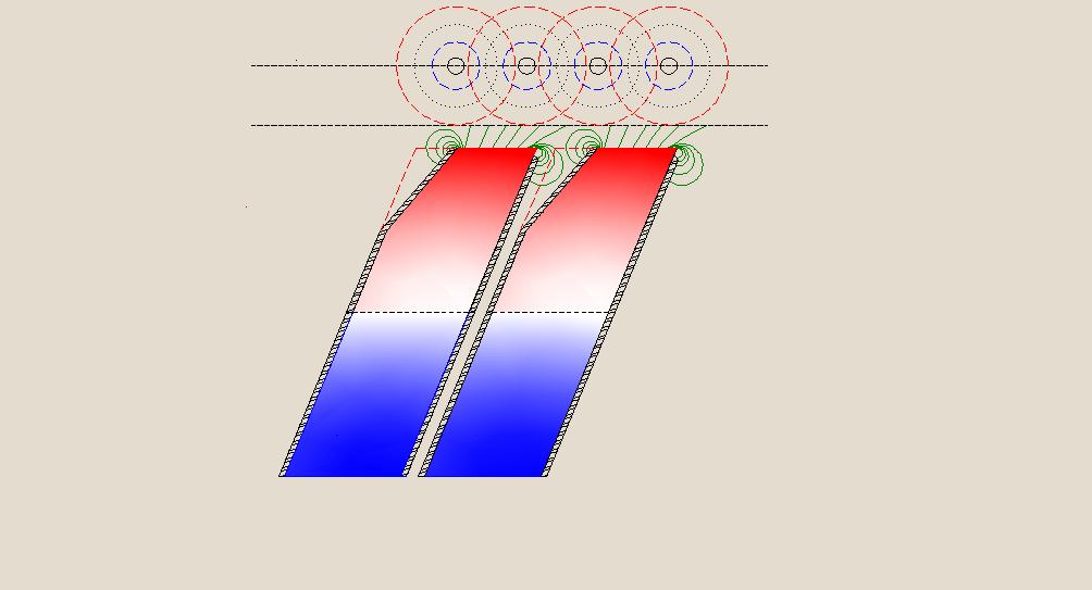
In order to achieve an even greater decrease of the inhibitory effect by the left parts of the pole’s surfaces of the stationary magnets, let's remove part of the mass of the magnets from the left side, as it shown in Fig. 30.
Such change of the form of the stationary magnet will increase the length of the air gap between left part of the pole surface of the stationary magnet and the surface of ring magnet of load which is approaching to it. As a result, the inhibitory effect on the movement of the load, in the direction which is determined by the influence of the vector Fext, will be weakened. In the bottom part of Fig. 30 are shown, for comparison, two curves of the change in magnitudes of the vectors ±FM(X) in dependence from the position of the center of gravity of the load on the trajectory of its movement. The curve corresponding to the application of a magnet without cut from its left side has the same form as in Figures 27 and 28, but here it is painted in a light brown color. The curve corresponding to the application of a magnet with a cut painted in dark brown color.
In Fig. 31 is shown a network of stationary magnets, each of which is analogous to the magnet that was discussed above. The magnets that form a network are located under the straight-line trajectory of the cylindrical load with annular magnets. At the bottom part of the figure are given the resulting curves, reflecting the effects of magnets on the movement of load along the axis X. And in this case, also for comparison, result of the interaction of magnets of moving load with the network of stationary magnets without cuts denoted in light brown color, but with the network of magnets with the cuts - in dark brown color.
Of course, the paths of the magnetic field lines, pictured here, which formed the basis for calculating the curves reflecting the impacts of magnets on the movement of loads along the axis X may differ from the real magnetic field distribution. However, whatever may be the real character of the magnetic field after such change of the shape of stationary magnet, the length of the air gap between its surface and the surface of approaching to him cylindrical magnet will be increased. That will inevitably lead to a weakening effect which impedes the movement of the loads in the desired direction.
Additional magnification of this positive effect can be obtained through the use of shielding the lateral surfaces of adjacent magnets. To do this, should be use high-permeability shielding alloys, i.e. the materials with much lower magnetic resistance than the air gap between the interacting magnets. Due to such screening of the lateral surfaces of the magnets, the force lines emanating from the some areas of the pole’s surfaces of the stationary magnets (the areas that are adjacent to side surfaces of their magnets) will be redirected out of the moving magnets, approaching to them. These force lines will pass through poles of theirs magnets, using the more easy paths - through screens.
In Fig. 32 is shown the cross section of two adjacent stationary magnets, the side walls of which are equipped with shielding covering.
*
* * *
Consider again the movement on a circular trajectory of cylindrical loads equipped with ring-shaped magnets. But in this case, we use the stationary magnets with all the positive changes described above (changes of the shape, of the magnetization direction, and the screening of the lateral surfaces). Now we can evaluate the impact of the stationary magnets on rotation of loads directly with the aid of vectors FM, without the need to decompose these vectors on theirs components FM(X) and FM(Y) .
If earlier at the rectangular shape of a stationary magnets (as it has been shown in figures 24, 25, and 26) only vector corresponding to the vector FM(Y) , due to interacting with the vector Fg, could positively affect the torque, but at this, not along the all circle, but only in the sectors 0° — 90° and 180° — 270°, then now vector, corresponding to the vector FM(X) , also makes positive contribution to the intensification of torque. Thus now, it is possible to count the torque, produced by the magnets in each point displacement of the center gravity of the load along a circular orbit, by multiplication the magnitude of the vector FM by magnitude of the shortest distance (d) between the direction of the vector FM and the rotation axis, as it is shown in Fig. 33. In this case is no need to consider the interaction with the vector of the gravitational impact Fg.
Consideration of Fig. 33 allows us to conclude that the use of the aforementioned improvements of stationary magnets provides an additional torque in any desired area of the circular trajectory along which center of gravity of the load moves.
Thus, finally, we have got a positive answer to the question, posed as the objective of the study produced in that appendix to the main text — “Providing of additional torque on the motor shaft is possible”.
*
* * *
In addition to the main result, for the sake of which was carried out this research, were revealed additional possibilities of using the interaction of permanent magnets in the repulsive mode. And though they are outside the basic purpose of all this work, as set out in the main text - "The development of gravity-magnetic engine" - they may be useful in the development of engines that do not use the effects of gravity.
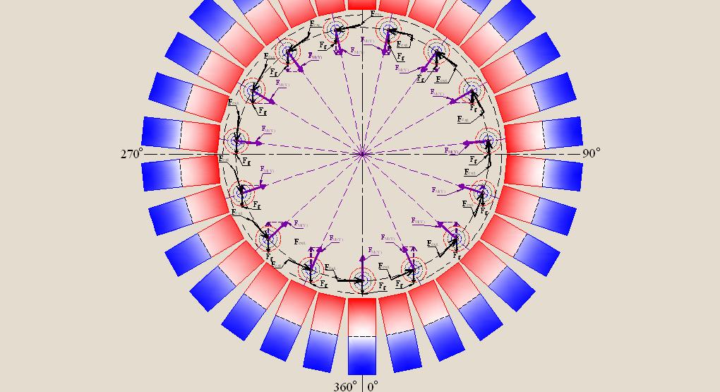
Let's consider Fig. 34.
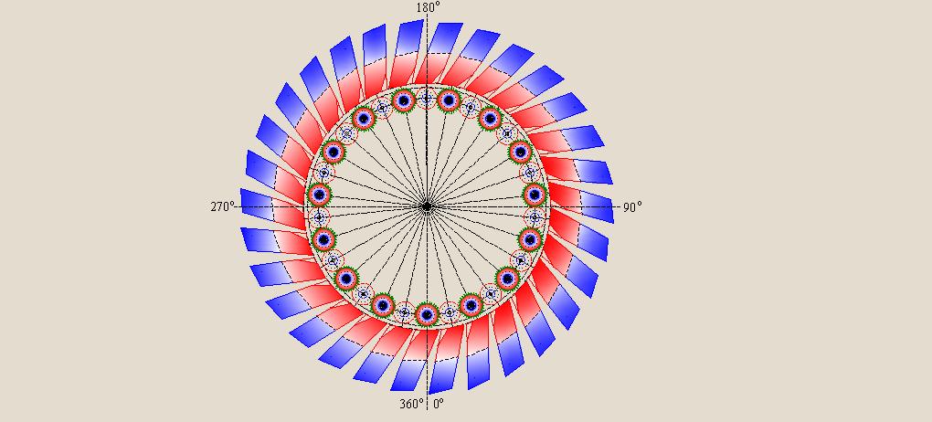
It is shown here a set of annular movable magnets uniformly distributed along a closed circular trajectory of motion, which is completely surrounded by the stationary magnets. The shape, the character of the initial magnetization, and screening of the stationary magnets correspond to the above recommendations. The stationary and movable magnets interact in the mode of repulsion.
As a result of the interaction between the stationary and movable magnets, during the movement of each load, at each point of the location of its center of gravity, is created a torque FM×d, as it is shown in Fig. 33. The sum of these torques forms the net torque, which may be greater than the sum of efforts that impede rotation of the motor shaft (friction, the payload on the motor shaft, the loss on heating, etc.). The net torque that generated only by the gravitational influence is equal zero in such a device, as it was shown in "Appendix 1". Thus, under certain conditions, here is possibly to provide the rotation due to the interaction of the magnets, without the use of the gravitational impact.
In this case, since gravity has no effect on the result of rotation, the plane, in which is located the trajectory of centers of gravity of the movable loads, can be positioned at any angle relative to the earth's surface. I.e., there is no essential restriction that is effective in respect to a gravity-magnetic motor. In engines that are similar to the suggested in the main text, which use the energy of the gravitational field of the Earth, this plane must be located only vertically relative to the earth's surface. Respectively, the axis of rotation of the rotor of any such motor has to be strictly horizontal to the surface of the Earth, i.e. perpendicularly to its shortest distance from the center of mass of the Earth.
The choice of ring-shape for magnets of the movable loads in the device that is considered in the main text is forced. In order to harness the kinetic energy of the gravitational field in that structure are ensured conditions for the appearance unequally lever arms for the centers of gravity of movable loads. This creates a torque on the motor shaft. But in this case, the trajectory of the cylindrical loads is such, that they must approach each other into the certain segment of their way (see figures 2 and 11 of the main text — sectors: a11 – O – a16 and a1 – O – a3). The necessity of rapprochement does not permit to choose as a form of magnets of the movable loads such form, which could be similar to the form of the stationary magnets. If such a possibility there would exist, then the efficiency of interaction there should be considerably higher.
Note.
The above paragraph has been written at the early stage of the designing, when it seemed that there was only one possibility of creating the motor rotor equipped with the mobile loads only of cylindrical shape. At the later stages of all this work on search the ways of creating of the engine that can run at the sharing of the kinetic energy of gravitation and energy permanent magnets the possibility of applying for the motor rotor of the movable loads equipped with magnets of the rectangular shapes nevertheless have been found! - Look into Appendix 4 – Option designing of motor rotor equipped by movable loads with permanent magnets the shapes of which are close to the shape of bar magnets.
If does not use the impact of gravity, and to place evenly the stationary magnets under the entire circular trajectory, as it shown in the Figure 34, then the change form of the movable magnets becomes possible. In this case the movable loads can be equipped with magnets which are similar to the stationary by form, i.e. with magnets of the rectangular form, but not of the annular form. This will optimize the interaction of the moving magnets with stationary magnets.
In Fig. 35 is shown the network of magnets which are moving along a rectilinear trajectory above the network of stationary magnets. The shape, the slope of the initial magnetization, and the screening of the lateral surfaces of the magnets of both networks are similar. The stationary and the moving magnets are facing each other by theirs surfaces of the same polarity, i.e. the force interaction of such networks is repulsive. Both oncoming surfaces of the approaching magnets are plane, so in this case is provided much greater efficiency of interaction of the magnetic fields, than in the case with devices using the movable magnets of annular form.
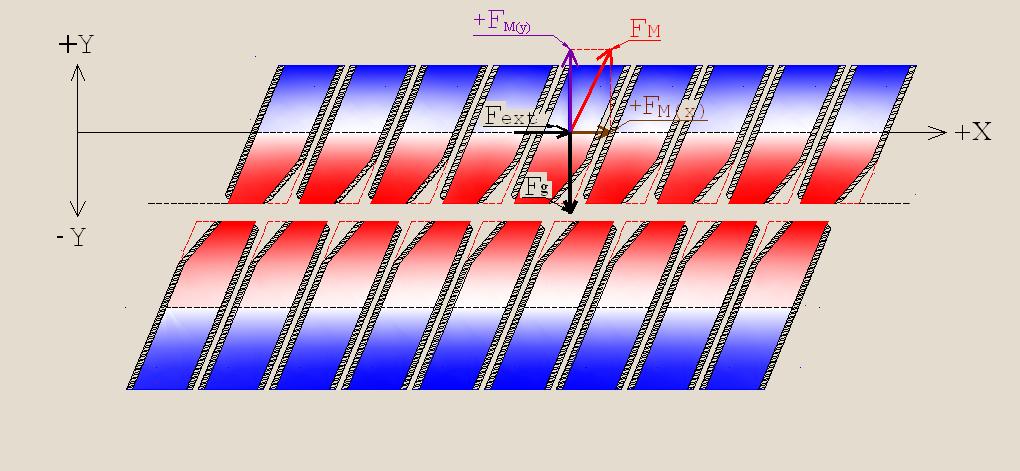
In such system of magnetic interaction is possible both the use of the phenomenon of levitation the masses of moving magnets, i.e., the weakening of the gravitational effect to their weights (the vector +FM(Y) has opposite direction to the vector Fg), and the use of the summation of the external force’s impact (Fext.) with result of the interaction of the opposing magnets (+FM(X)).
The effect of levitation during the motion of magnets along a rectilinear trajectory above a network of stationary magnets can be used only under the condition of ensuring by technical means restriction of the possibility deviations of the moving magnets from the location along a single axis with stationary magnets[6],[7].
From the consideration of Fig 35 can be supposed that, under certain conditions, it will be possible to ensure movement of the upper network of magnets along the axis +X even without impact of the external force (Fext). At this, the sum magnitudes of the vectors +FM(X) (the resultant force action of magnets to that direction) must be greater than the sum of the forces impeding to this movement.
*
* * *
As a result of research considered here, was confirmed the possibility of providing additional torque on the shaft of the motor which had been proposed in the main text.
Here are provided the recommendations for increasing the efficiency of use permanent magnets in motors, where the magnetic energy is used in conjunction with other energy sources. It should be noted, that the recommendations contained herein are in need of experimental verification and, especially, in the deeper theoretical analysis in order to reduce the costs of labor and time for the experimental testing during real designing.
The results of research may be more accurate, if the interaction of magnetic fields will be studied in three-dimensional space rather than in two-dimensional, as it has been done here.
The results of the investigation allow also make assumption about the some possibility implementation of engines which use only the energy of interaction between the magnets.
Note.
At this, it should be pointed out that the conclusion of the feasibility of the motor by using only the energy of the magnets (?) ... seems to the author of these lines too "optimistic". To prove this conclusion, it is necessary the more profound theoretical basis and experimental confirmation.
This page was last modified on 24 September 2014